
Five Steps Towards a Successful Wind Turbine Gearbox Inspection
Introduction
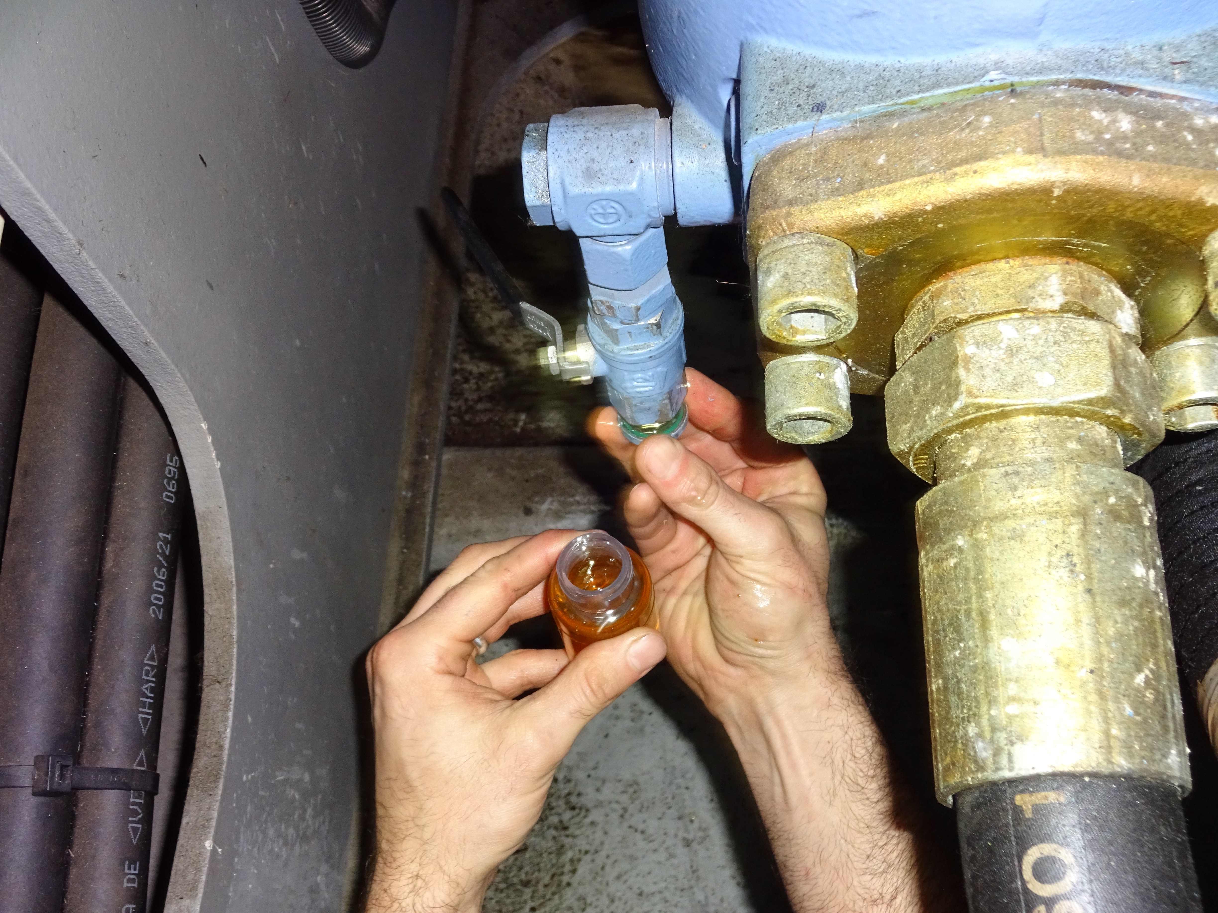
A wind turbine gearbox inspection usually comprises at its core an in-depth visual endoscope inspection with the option of an additional oil sample taken from the existing oil, which is sent away to a dedicated oil laboratory for spectrophotometric and particle analysis.
Although highly commendable, the problem with relying on mainly a visual inspection method is that some components in the high speed helical gear section of the gearbox are often below the internal oil level and obscured from view. Additionally, the low speed planetary section can present further challenges whereby only a small section of the circumference of the ring gear is visible. Some gearbox manufacturers have added heat shields that obscure bearings or contain oddly designed internal castings which completely block the route of the endoscope probe, making visual inspections particularly challenging and in many cases, preventing inspection of major components.
Finally, no matter how detailed or in-depth the endoscope inspection may be, there is no definitive way of determining the overall operational condition of the gearbox unless additional data is obtained.
During the past several years of undertaking thousands of wind turbine gearbox inspections, we have developed and perfected a best practice approach and approved method for carrying out end of warranty gearbox inspections which is discussed here at some length.
Step One: Using Your (Common) Senses!
- Unusual low-pitched droning sounds emanating from the nacelle may indicate a high speed bearing failure either on the gearbox or generator
- Knocking sounds could be an indication of cracked gear teeth, increased backlash (lateral loading) or wear of the sun-wheel pinion gear
- Oil dripping from beneath the outside of the nacelle or down the internal tower ladder may indicate a damaged gearbox seal or leaking pitch cylinder
- Unusual odours due to rapid and extreme heat of the internal gearbox oil or incorrect oil type / incorrect mix of synthetic and mineral oil which may have been inadvertently added to the installation
- Discuss the history and recent findings with the wind farm operator's authorised technicians who will give invaluable insight into the machine condition or any recent maintenance carried out on the installation before any technical data is collected
Step Two: Acoustic Analysis
Before isolating the wind turbine and ascending the ladder, a sound reading can be obtained inside the base of the tower with the wind turbine still in operation.
Ensuring the tower entrance door is completely closed with no interference from any extraneous noise or wind, a fifteen second real-time sound recording can be captured at the base of the tower via a microphone using a sophisticated Sound Level Meter, with FFT (fast Fourier transfer) functionality and an onboard recording module. This reading enables us to determine the combined low, mid-range and high-frequency attributes of the gearbox and generator before we ascend the wind turbine.
Unless there is a very late-stage bearing wear, the recorded result cannot determine the individual component condition quite as precisely as when using vibration analysis for instance, however, it is possible to highlight areas of concern with either the gearbox or generator which can serve as a very useful 'heads up' assessment before implementing more in-depth non-destructive testing techniques within the nacelle.
Ideally, acoustic analysis should be implemented in advance during a separate visit on all the wind turbines in succession. A single reading take less than twenty seconds to collect and as data is obtained very quickly at the base of each wind turbine under similar wind speeds, an entire wind farm can be completed typically in less than a day! The results from this data can then determine which turbines are operating within specification and those that require further investigation using additional techniques.
Acoustic analysis also serves a useful means of cross-referencing the additional data obtained using vibration analysis.
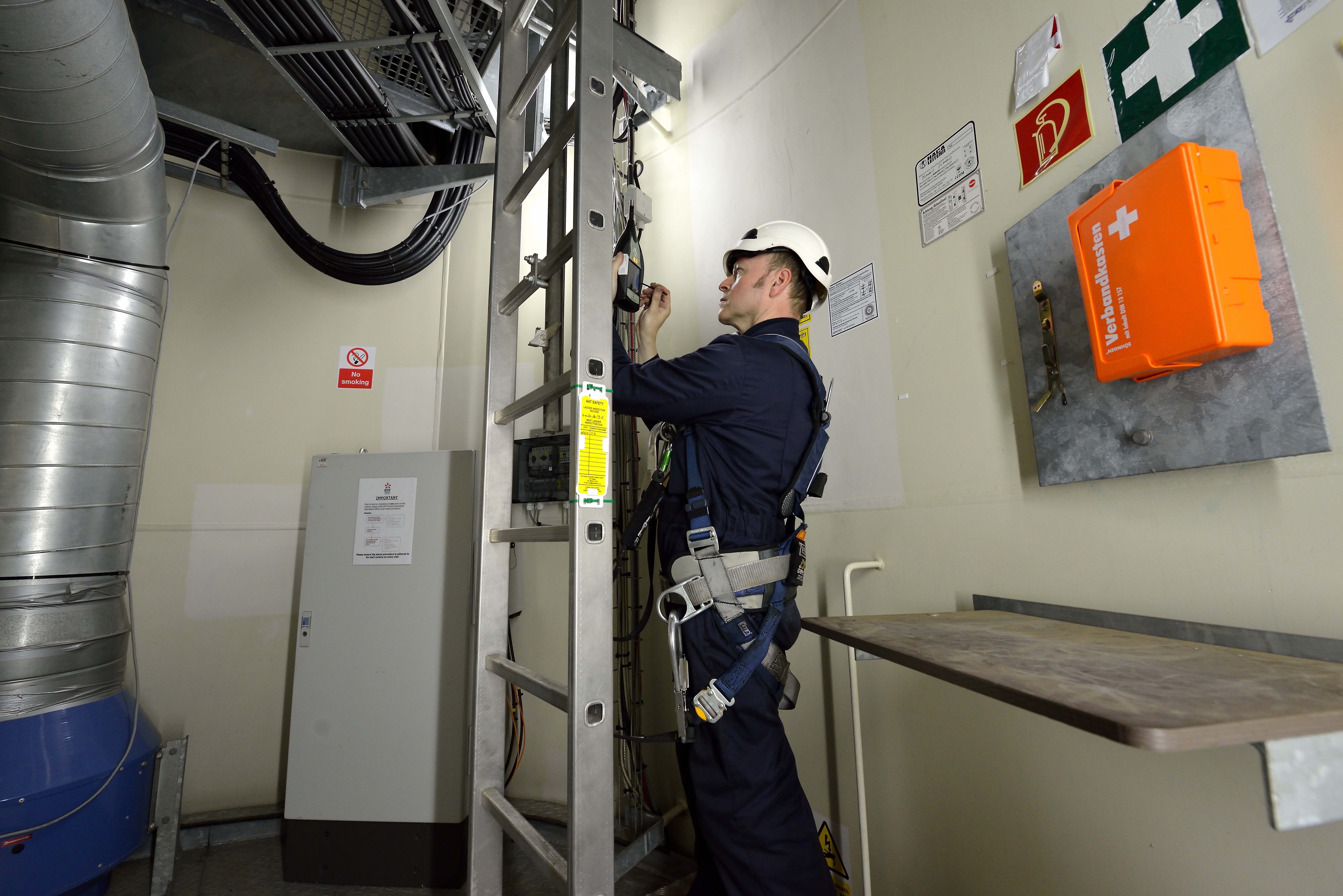
Step Three: Initial Inspections & Oil Sample Collection
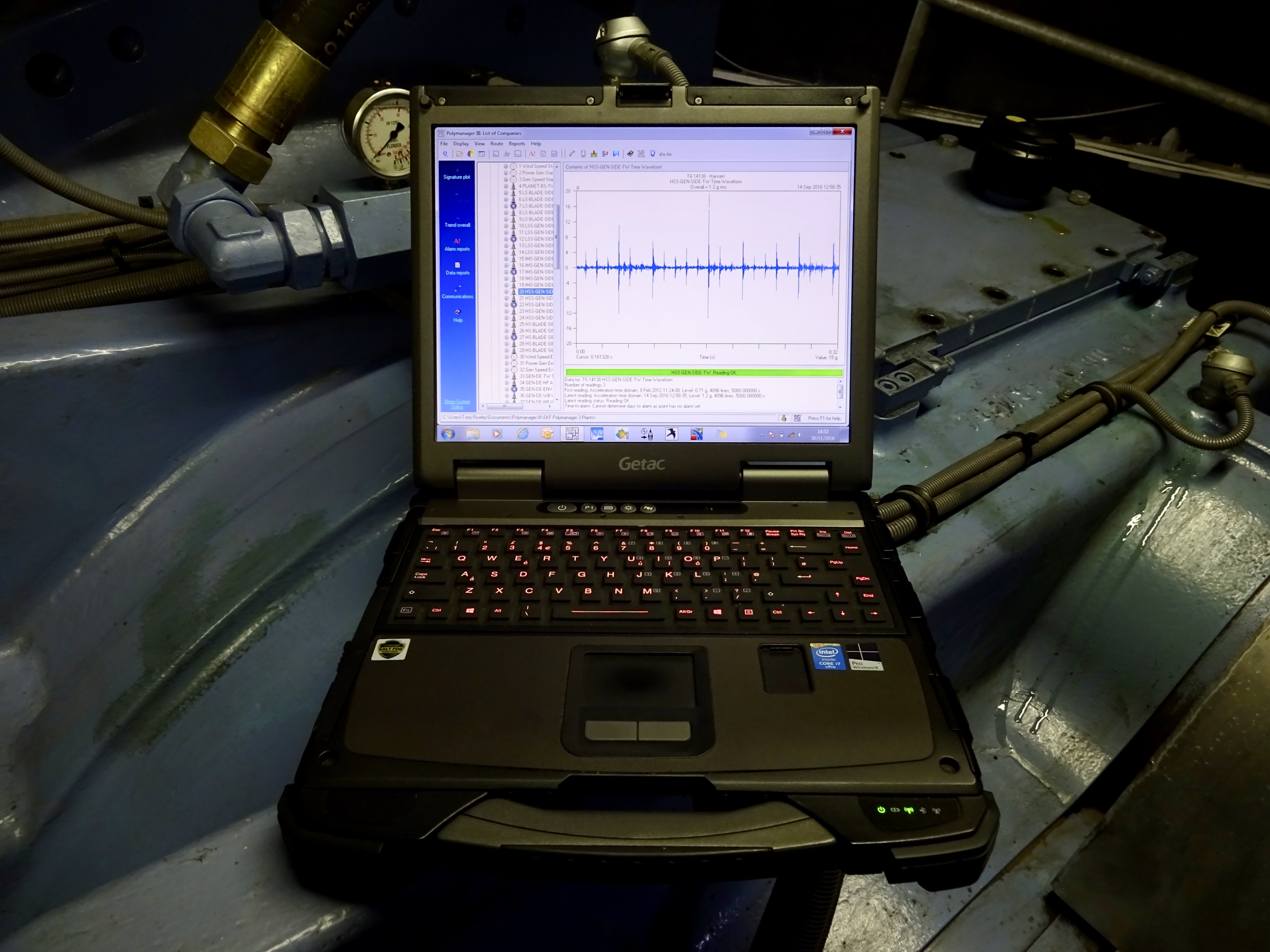
Step Four: Vibration Analysis
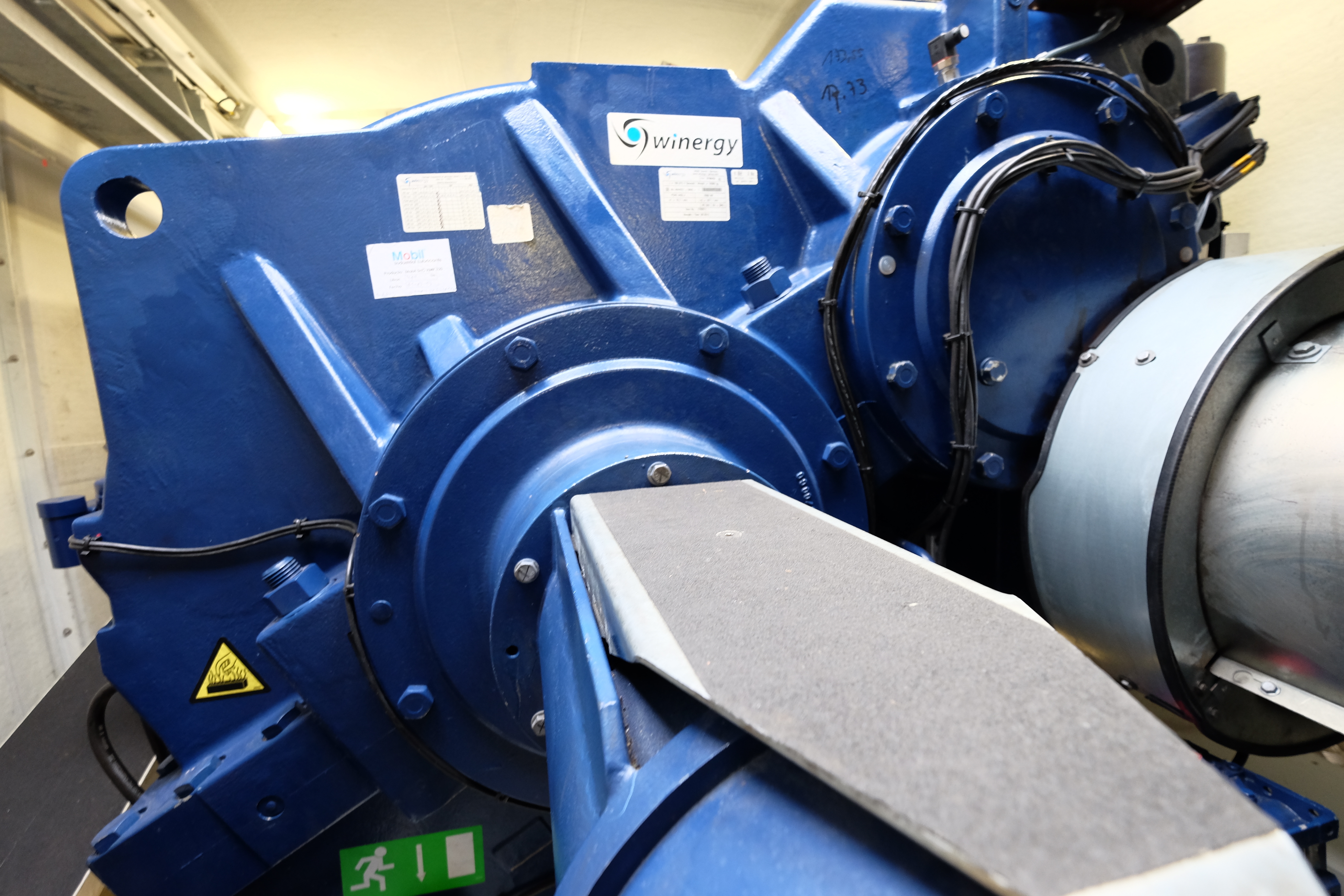
If a CMS (condition monitoring system) unit has been installed on the gearbox, it is advisable to check the accelerometers for any loose or damage cabling, incorrect positioning, loose or improper fit, oil contamination, heat damage, falsely labelled or incorrect termination etc. The CMS sensors may have been inadvertently damaged during any routine maintenance or repair work on the gearbox and a functional integrity test of the entire system should be performed to ensure the system is monitoring correctly and not producing any false alarms or inaccurate readings.
The main advantage of undertaking vibration analysis prior to conducting an endoscope inspection is that any areas of potential concern are quickly and accurately identified, so that the endoscope engineer has essential information on where to concentrate and intensify the remote visual inspection in a particular area of the gearbox.
The first task before undertaking any vibration analysis on the gearbox (once all brakes and other H&S restrictions are in place) is to ensure the external surfaces of all the main bearing locations are cleaned of any oil or brake dust (or usually both) before positioning any accelerometers onto the gearbox. The sensors should be fitted with high strength magnets or 'quick-fit' adapters and placed in the radial plane directly above each bearing housing (ideally, on a flat surface), with all cables secured tightly around the body of each sensor (in order to eliminate unwanted cable movement and vibration). Particular attention should be made to ensure the correct type of sensor is used at each section of the gearbox, for instance, on the low speed section of the gearbox, it is advisable to use a high-sensitivity/low noise accelerometer in place of a standard general purpose accelerometer, in order to improve signal frequency response for the very low frequencies (and amplitudes) generated by the planet carrier bearings, planet gears and sun-wheel pinion.
In addition to placing sensors on the gearbox, it is highly recommended that the generator bearings should also be included in the analysis, not only to determine the condition of the generator bearings per sé, but in order to distinguish between any potential transmissive vibration from worn generator bearings being inadvertently detected on the high speed bearings of the gearbox. By not including the generator bearing analysis, we risk misinterpreting any high amplitude vibration occurring on the high speed shaft bearings of the gearbox which can result in potential misdiagnosis, particularly as the bearing defect frequencies and running speeds are identical in many cases.
The sensor cabling from each accelerometer should be neatly loomed and if necessary, tie-wrapped out of harm's reach away from any exposed rotating shafts or other hazards in and around the gearbox, generator and main shaft etc. The trailing cables of each accelerometer should be wired into a junction box with a selector switch for each channel pertaining to the various sensor locations on the gearbox (and generator). At this stage, the junction box should be carried down to the lower yaw deck and all personnel should vacate the nacelle and accompany the vibration analyst in this safe work area.
Once the access hatch to the nacelle has been closed and all personnel are positioned safely in the lower yaw deck, we can remove all isolations and the wind turbine can be put into operation and a vibration analyser can be connected to the junction box.
We are now at the mercy of the elements! Ideally, we would like a constant wind speed and direction, with little or no variation of approximately 8-10 m/s to give ample high and low speed vibration amplitudes to enable us to easily identify and assess potential issues affecting the gears, bearings and mechanical attributes of both the gearbox and generator. However, this is seldom the case and in reality, the analyst has to cope with varying wind speeds and loads as well as occurrences of gearbox resonance, backlash and intermittent 'spikes' and 'impacts' caused by yaw drives and oil circulation pumps actuating during data collection. Other factors such as tower movement/sway and altering blade pitch angles also have an influence. As a general guideline, the following rules should apply when taking vibration readings on a wind turbine gearbox and generator:
Wind Speeds Below 3 m/s and Above 15 m/s
During a very low wind speed (i.e., below 3 m/s) or too high
a wind speed (i.e., above 15 m/s), data collection will have to be abandoned
until wind speeds become more favourable (and safe in the case of wind speeds
at or above 15 m/s) for the tests to be conducted.
Wind Speeds Between 4.0 m/s and 6.0 m/s
In the case of low to moderate wind speeds (i.e., 4.0 m/s -
6.0 m/s), analysis can still be performed as the high speed gears and
associated gear mesh frequencies are now operating at an optimum frequency and
become more audible and easily identifiable (especially in the case of cracked
gears, backlash and/or bearing-related issues), so in some circumstances, this
can be seen as beneficial to the analysis rather than a hindrance. However, the low speed section of the gearbox will be generating very low frequency vibration and unless a late-stage or pronounced fault is present, vibration amplitudes will be generally subdued. This requires special considerations with regards to applying a higher resolution to our spectral analysis and implementing real-time recorded analysis in order to highlight any underlying issues in the planetary section of the gearbox.
Wind Speeds Fluctuating Rapidly or Erratically
In the case of any erratic
fluctuation of wind speed, data can still be collected when the mid-point of
the lower and higher wind speeds/overall vibration amplitude is observed on the
analyser and data will be averaged during the increasing/decreasing speeds.
There is also the benefit of observing the installation operating at variable
speed throughout the entire operating range of frequencies, so
any critical shaft speeds or resonance frequencies can be readily identified,
particularly when utilising a real-time recorded sample trace technique.
The vibration data should be collected from each monitoring point and include: synchronous time waveform signatures, unfiltered high frequency acceleration spectra, filtered 'enveloped' acceleration spectra and velocity spectra, as well as real-time recorded analysis. More importantly, the vibration analyst should be adequately experienced and qualified to undertake the analysis with detailed knowledge of the following:
- Type of bearing at each monitoring point
- Defect frequencies of each bearing
- Type of gears in use (helical, pinion, spur wheel etc.)
- Gear mesh frequencies (number of gear teeth multiplied by rpm of each gear)
- Configuration of internal gear train and gear ratios
- Known resonance 'bands' observed during speed changes
- Gearbox type (some gearboxes are prone to more 'backlash' and 'end loading' than others)
- Awareness of vibration transmitted from other sources (oil circulation pumps)
- Varying degrees and progressive stages of bearing and gear wear
So, what are we trying to determine using vibration analysis?
- Cage, roller (or ball), outer and inner race defects with each bearing
- Cracked, worn, rough edged, loose fit or skewed gears
- Eccentricity or misalignment between gears
- Wear on the low speed sun-wheel splines
- Wear or rough edges/damage on the planetary slew ring and planet wheels
- Incorrect interference fit or wear in bearing housings
- Bearings not pre-loaded when installed in the gearbox
- Excessive lateral movement, 'backlash' or 'end loading'
- Incorrectly machined gears
- Heavy 'spots' on bearing rollers and/or gears
- Imbalance
- Misalignment
- Looseness
- Transient (intermittent) vibration or knocks
- External coupling and brake disc imbalance, misalignment, looseness or wear
- Establish the installation is operating within acceptable ISO approved standards
Once
the final reading has been collected from the installation, we can stop the wind turbine,
re-apply all the necessary isolations and brakes before re-entering the upper nacelle region. We can then safely remove
the magnetically (or quick-fit adapter) mounted accelerometers from the gearbox.
The results of the analysis should now be discussed in detail with the endoscope inspection engineer highlighting any particular areas of concern.
In conclusion, a thorough vibration analysis survey should be able to precisely determine the source and nature of the fault (or faults) down to individual component level, as well as establishing the overall operational condition of the installation before any remote visual inspection is carried out. Clearly, this type of knowledge is of great benefit, not only to the endoscope inspection engineer who is about to undertake the remote visual inspection, but to the client, who has a detailed and thorough assessment of the installation, making judgement calls on whether to restrict the speed or isolate the wind turbine a relatively straightforward process.
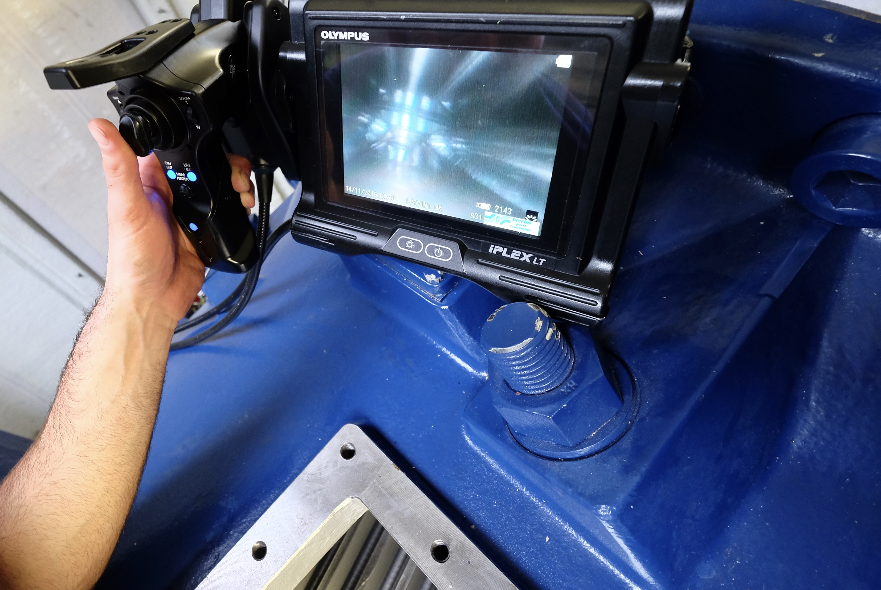
Step Five: Endoscope Inspection
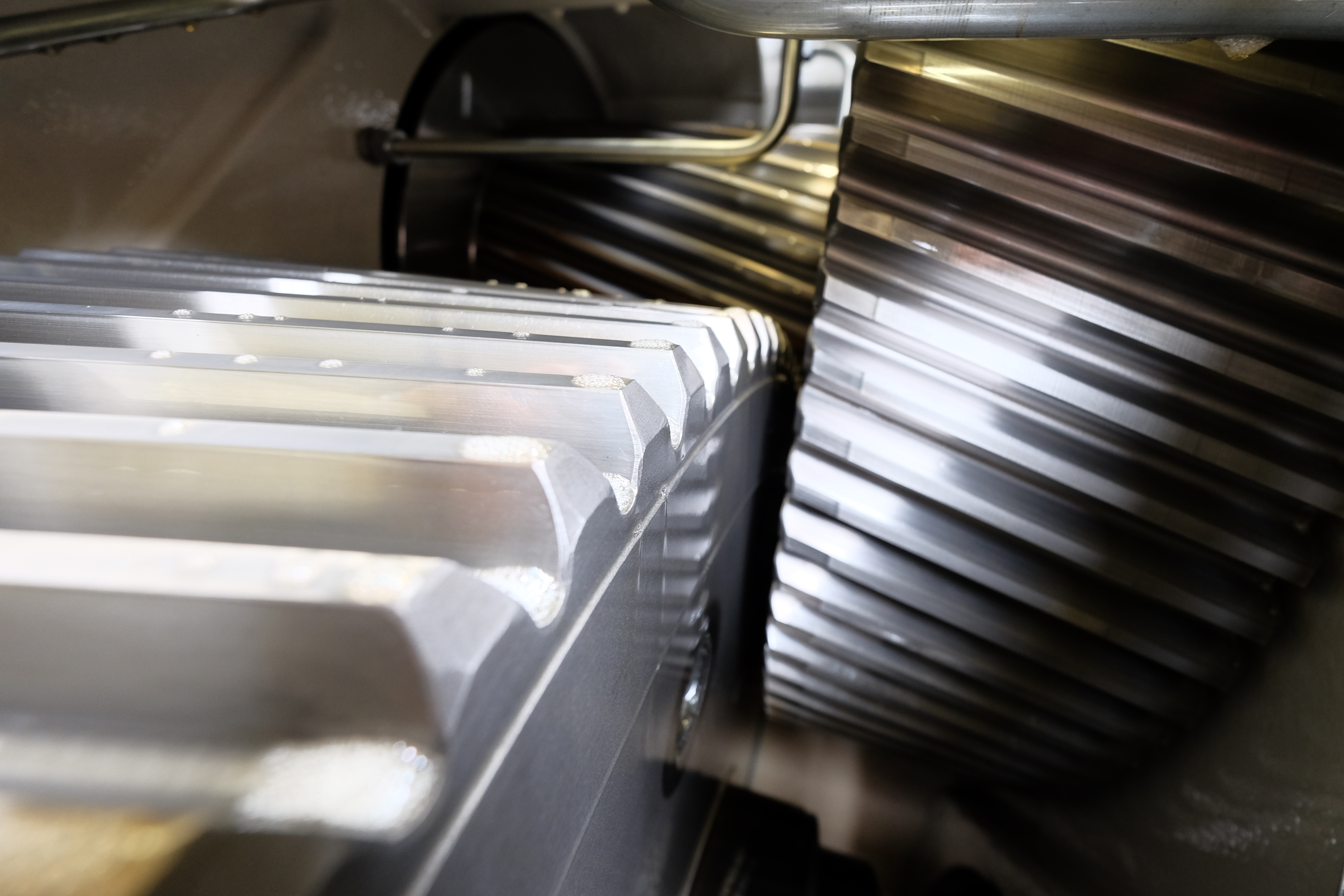
Before we commence our endoscope inspections, we have to apply the brakes, pin the rotor blades, deactivate the circulating oil pump and ensure all the necessary isolations are in place. Once confirmed, we can proceed to take the covers off the high speed helical section of the gearbox (as long as wind speeds are below the maximum safe working limits) and allow the gearbox to cool down over the next 10-15 minutes. Using a digital camera in macro mode, we can collect images of the gears and if necessary, individual gear flanks, making notes of any unusual markings, stand still marks, scoring, scratching, pitting or further damage.
Upon completion, we can begin the endoscope inspection of each bearing in the high speed helical gear section of the gearbox. The endoscope should be an industrial-grade high end model, fully articulating with adjustable high intensity lighting and a high resolution screen and clear image output, with a probe diameter no more than 4.0 mm in order to allow easy access in-between the rollers of the bearing. Once the probe has been inserted between the rollers, a series of images should be captured along the length of the rollers (entrance point, mid way and end point), another with the cage and races in view and finally, another image showing any possible end-loading on the faces of each roller. It is important to keep the probe lens (and filter, if fitted) completely clean between each bearing inspection using an alcohol based cleaner and lens tissue, in order to prevent any oil droplets permanently adhering to the probe lens element, which will eventually render the images unusable. The procedure should be repeated again on the same bearing in-between another set of rollers at least two more times, before moving on to the next bearing in the gear train using the same techniques.
Once the final set of images has been obtained from the high speed section of the gearbox, we can replace the gearbox cover plate and move on to the low speed planetary section. There is usually a single cover or in some cases, two cover plates on the planetary section of the gearbox, which conveniently allows access to the low speed planet carrier bearings, planet wheels, planetary outer gear ring and sun-wheel pinion and bearing. We need to rotate the rotor blades to gain access to the three planet wheels in the low speed section of the gearbox and this requires the rotor blades to be pinned and locked securely into place once the planet wheels come into view in either or both of the inspection hatches. As when inspecting the high speed helical gear section of the gearbox, we need to ensure all the additional isolations are in place before we can safely resume our remote visual inspections.
So, what are we trying to determine using an endoscope?
- Varying degrees of bearing and gear wear
- Micro-pitting to heavy-pitting
- Scuffing and uneven wear patterns
- Carbonisation and effects of high or increased temperatures
- Particle wear
- Fractures
- Fatigue, stress, corrosion and cracking
- Light and heavy grooving or scoring
- Spalling
- Heavy 'spots' on bearing rollers and/or gears
- False and true brinelling
- Loading anomalies
- Adhesive wear
- Plastic flow
- Friccohesity
- Abrasive and erosive wear
- Fretting
- Heavy running marks
- Fluting and arcing effects
Once
the final image has been taken and stored on the endoscope, we can replace the gearbox cover plates and discuss the findings of the inspection with the O&M site technician.
Conclusion
An over-reliance on one form of non-destructive testing technique coupled with a complete disregard to any influencing external factors (mechanically-induced or otherwise) can inadvertently lead to the misdiagnosis of a wind turbine’s gearbox mechanical and operational condition, with a potential for a catastrophic gearbox failure occurring well before the next scheduled inspection date.
Although the gearbox components may appear to be visually intact at the time of the inspection, an existing wind turbine fault such as a worn or damaged coupling on the high speed shaft or faulty pitch actuator causing a turbine blade to induce a high level of imbalance on the main shaft bearings will eventually induce significant secondary wear on the gearbox, by which time a relatively simple and straightforward repair will become a very expensive and time consuming business at a later date unless rectified during (or shortly after) the time of inspection.
In conclusion, a thorough end of warranty wind turbine gearbox should comprise of the following:
- a methodical, systematic and repeatable approach
- a complimentary set of condition monitoring technologies and techniques
- expert engineering knowledge and relevent experience
- an account of the additional wind turbine mechanical components and external factors
- sharing of information between O&M engineers and contracting companies
Finally, correlating the findings of the gearbox inspections with any unusual noises, resonance, vibration or temperatures and discussing in detail with the site O&M technicians will help raise awareness and may also prevent the next catastrophic gearbox failure occurring on site; the sharing of information is key.

Article written in February 2017 by Tony Riseley, Director of Windnostics Limited.
© Copyright 2017
® All Rights Reserved
Unauthorised use and/or duplication of this material (text and images) without the express and written permission from this site's author and/or owner is strictly prohibited. Excerpts and links may be used, proved that full and clear credit is given to the author and Windnostics Limited with appropriate and specific direction to the original content.
DISCLAIMER
The information and views set out in this article are those of the author and do not necessarily reflect the official opinion of Windnostics Limited. Neither Windnostics Limited, associated institutions and bodies nor any person acting on their behalf may be held responsible for the use which may be made of the information contained therein.
The author has made considerable efforts to present accurate and reliable information on this website. However, Windnostics Limited and the author do not take any legal responsibility for the accuracy, completeness or usefulness of the information herein and shall not be liable for any damages or injury arising from the content published on this website.
Other websites may link to this site with or without the knowledge of Windnostics Limited or the author. Links to external websites do not imply endorsement or approval of those sites or the information they contain. Windnostics Limited and the author are not responsible for the accuracy of the information, the content or the policies of such sites and shall not be liable for any damages or injury arising from the content or use of those sites.
This website may refer to organisations, businesses and other resources available through the government, non-profit and commercial entities. Referrals to such entities are provided solely for informative and educational purposes only and as a convenience to the user. A reference to a product or services on this website should not be considered an endorsement or recommendation of that product or service. Windnostics Limited nor the author shall be liable for any damages or injury arising from the use of or connection with such products, services or entities.
PRIVACY
Windnostics Limited does not collect or share personal information from users of this site. The only exception to this general rule is in the case of harassing or otherwise threatening or explicit emails or contacts, which will be reported to the proper authorities.